Party Machine
Music, lights, and bubbles at your fingertips
Controller Glove
by Chue and Melody
Overview
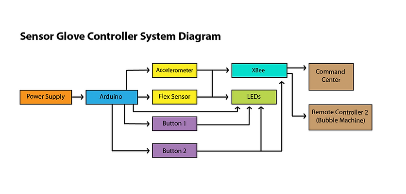
The glove controller is composed of a 6V battery, buttons, LED lights, flex sensors, an XBee, and an accelerometer. The flex sensor controls the amount of bubbles produced by the bubble maker and the accelerometer detects gestures that control the bubble maker's movements. The LED lights act as actuators to show change in sensor values. Buttons are used to turn on/off LED lights and stop the bubble maker's movements. The glove sends data through the XBee to both the command center and the bubble maker.
System Diagram
Here is a simple block diagram of my project that illustrates the major hardware components of the system and how they are interfaced to the Arduino.
Implementation: How the Glove Works
The glove controller is composed of a 6V battery, buttons, LED lights, flex sensors, an XBee, and an accelerometer. By pushing one of the buttons, the controller would turn on/off LEDs on the glove. This would also give us a feedback that our code and our button are working. The LEDs are also used to signal a change in the flex sensors and if data is sent through the XBee. When we flex our fingers, the the flex sensor send send a flex value (0 = no bubbles, 1 = one bubble gun, 2 = two bubble guns) to control the amount of bubbles. The more the finger flexes, the more bubbles would be generated. We utilized the accelerometer to detect change in hand movement (such as moving the hand up and down). If there is enough change in one direction, we would send a message to the Bubble Maker, causing the bubble maker to rotate (or jitter). We also have a button that sends commands to stop the motion of the bubble maker.
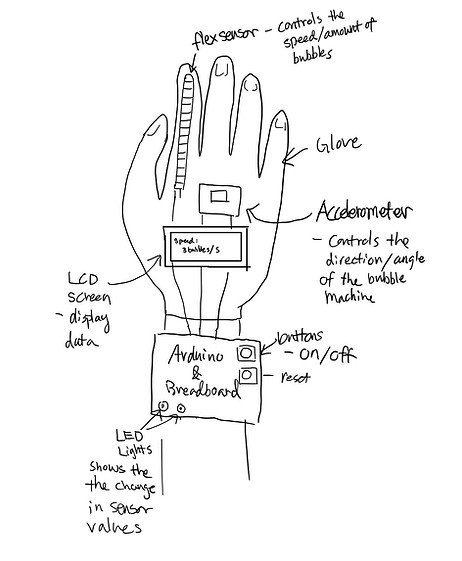
Initial Idea Sketches
The LCD is replaced with LEDs and position of sensors is modified. We also decided to use fixed gestures (such as moving the hand up and down) instead of rotating the hand to control the movement of the bubble maker.
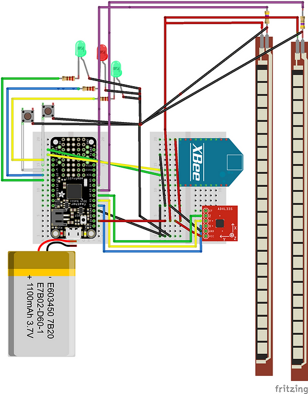
Breadboard Layout
We used the Fritzing application to show the electronic circuit.
Software: Design and Approach
Our approach for creating the remote controller was to test out each component prior to integrating all the parts together. We started with letting each part having its own code. This allowed us to test parts separately at any time during the development phase to ensure that each part is working correctly, which helped with debugging. For example, we wrote the codes for the flex sensors and the accelerometer separately and tested both of these codes separately before integrating them. After integrating, we often had problems with the sensors and had to come back to the original codes for detecting abnormalities. After making sure that the two major components are working correctly together, we added buttons, LED lights, and the XBee. Once all parts were integrated, we started thinking about the physical design of our project. Since we planned on having a wearable, it was important to us that the controller would be clean and compact. We decided to switch the Arduino Uno for an Adafruit Feather microcontroller for a smaller size and easier movement.
Sending Messages to the Command Center and Bubble Maker:
To communicate with other stations, we are sending the following messages through the Xbee.
Note: "id:bc” is the identification for this remote site, so other sites would know that the command is coming from the controller glove. The code after the "|" indicates what kind of data is being transmitted, followed by its value.
"id:bc|bubMode:0" // No Bubbles
"id:bc|bubMode:1" // One bubble gun makes bubbles
"id:bc|bubMode:2" // Two bubble guns make bubbles
“id:bc|gestMode:0” // Bubble maker stops moving
“id:bc|gestMode:1” // Bubble maker moves (Jitterbug Mode)
Click for Controller Code
Our Process
Sensor Challenges
We had difficulty controlling the sensors and getting consistent, reliable data. Most of our time was spent on testing sensors and calibrating them to get the desired values. Having a slightly different positioning of the flex sensor and accelerometer would sometimes invalidate the data collected. We have to be extremely careful with the sensors. Flex sensors were sensitive to movement of the fingers or movement of the gloves. When the they were sewn onto the gloves, certain parts buggle up (due to different finger lengths and the knuckle location). Over time, with constant testing and transporting them around, one of the flex sensors broke at the base. Luckily, we had a few spare flex sensors and was able to replace, resolder and resew the broken flex sensor back on the glove.
Even though the accelerometer was working, it was also sensitive and noisy that we had to tweak the code multiple times to ensure that it was working consistently. To reduce the noise, we wrote code that would only return an average acceleration value over multiple interval points (20) and over a period of time (1 second). In order to get a consistent value for capturing a specific gesture, we decided to detect gesture by capturing a huge change in one axis. Initially, we had code to detect four different types of gestures: moving the accelerometer “left and right”, “back and forth”, “in a circle”, and “up and down”. However, we ended up only using one gesture to reduce the engineering demands on another part of the project.
Issues with Buttons
We had a problem of detecting button clicks. The user sometimes has to click the buttons multiple times before getting a response. We believe that this is due to the delay in the loop section of our program. The loop section contains/calls many lines of code, and delays naturally as the program processes the code. This resulted in increasing the time interval before checking for clicks, which leaves clicks often go undetected. We didn’t use the button library for this project because we thought having additional button gestures (such as press hold) was unnecessary. However, using the button library could have been helpful for detecting when a click happens.
Wires and Breadboard
Another challenge for us was how do make our physical product more compact and at the same time have everything connected securely. Once the code worked, we were able to switch from the Arduino Uno to the more compact Adafruit Feather, but we still had to deal with organizing wires and preventing them from slipping and falling off the breadboard. We feel that we could have solved both the bulky issues and the wires coming off if we were able to solder some of the components to something like a solderable perma-proto half-sized breadboard. This would allow the wires to be secured without us continually having to check the connection and also allow us to have a less bulky look.
Conclusion
As a whole, this project was a valuable experience for us to get creative, build something by ourselves, learn about physical computing, get team working experience, and collaborate with people coming from different backgrounds. Communication was crucial to the team’s overall success, as we all had to constantly check in with each other and understand where we are at in order to move forward. It was common for us to adjust our parts of the code based on what the other teams need. There were also stressful times when everyone was frustrated because we couldn’t figure out why something wasn’t working for hours, and we had to stay up late at night debugging and modifying the code. Looking back, all the hard work was worth it. Seeing our demo working on presentation day was extremely exciting and rewarding.
Additional Resources: Linked that helped us with this project
https://learn.sparkfun.com/tutorials/flex-sensor-hookup-guide
https://learn.adafruit.com/adafruit-analog-accelerometer-breakouts/calibration-and-programming
https://chionophilous.wordpress.com/2011/08/26/accelerometer-calibration-ii-simple-methods/
https://learn.adafruit.com/adafruit-feather-32u4-basic-proto/using-with-arduino-ide