Party Machine
Music, lights, and bubbles at your fingertips
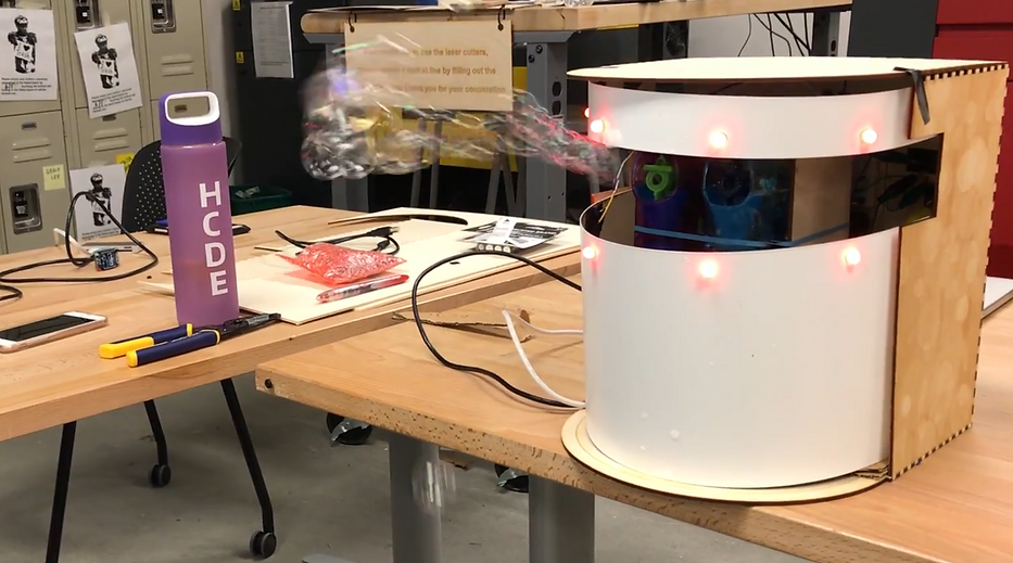
Bubble Maker
By Lauren and Mike
Overview
The Bubble Maker component is controlled by two Arduino units: Display & Interface and Turret. Two Arduinos were needed for this project to accommodate all the necessary digital pins to power and control our sensors and actuators. The Display & Interface (D&I) unit controls the LED strip, LED display, buttons, touch strip sensor, and light sensor. The touch strip adjusts the brightness level of the LED strip mounted to the front of the enclosure. The color of the LED strip is determined by the ambient lighting in the room using data from the light sensor. Additionally, the LED strip has several different modes that can be selected using a button input. The D&I is also the link to the Command Center component and regularly sends status updates (color mode and current color) via XBee communication. Because the D&I handles all direct inputs for the Bubble Maker, it also uses the XBee to relay the power state to the Turret unit. The Turret unit controls a stepper motor (using an Arduino motor shield) and two servo motors. The physical turret is comprised of a platform connected to a base using the stepper motor. Mounted to platform is two bubble guns which are mechanically connected to the two servo motors in order to control each gun’s trigger mechanism. Finally, the Turret unit uses an XBee to receive inputs directly from the Controller Glove component which is used to manipulate the flow of bubbles from the bubble guns and rotate the turret.
System Diagram
This block diagram shows all major hardware components for the Bubble Maker's two Arduino units: Turret and Display & Interface.

Breadboard Layouts
The following layouts diagram the electronic circuits for all major hardware components for the two Arduino units: Turret and Display & Interface.
Arduino 1: Turret

Arduino 2: Display & Interface

Software
To design the software that was used to power the bubble maker, we started by learning how all of the different hardware components worked and created sketches to control them individually. As each component was figured out and rough drafts of code were written, different sensors and actuators were combined into sketches to confirm their compatibility. As our choice of sensors were solidified and all of the parts were defined, we decided to split the parts into two Arduinos, partially because the number of available pins and, additionally, because of the complexity of coordinating the software between two people.
There were several issues with the motor that was used to rotate the turret. First, the motor was not connected to a modern motor shield and, therefore, we did not have access to any pre-built Arduino libraries. With no libraries to use, all coding had to be done manually, which was cumbersome. Issues arose when we attempted to remove the numerous delays from the stepper code and replace them with millis offsets. Without the delays, the system’s timing seemed to be off and was unable to reliably rotate the platform. Rather than rotating, we had to settle for the motor performing a shaking motion when triggered from the glove through the Xbee.
The other Arduino held all the buttons and sensors that controlled the lights, sending updates through the XBee to the master control. The sensors, displays, and lights didn’t pose any significant issues and the most difficult part came in making sure that all of their code worked together consistently and without interruption.
Project Code Files
Process
This project was an ambitious and creative project that we hoped would be something that hadn’t been seen before in HCDE 439. We knew at the start that we wanted to do something fun, and after perusing available sensors and looking at examples on Pinterest, we identified the idea of a bubble machine, paired with lights, music, and movement to create an interaction that you may find at a party of some kind. From there we used the project outline to define the necessary components for each: two local inputs, two sensor inputs, a local display and a local actuator in each of the remote teams and the command center, messaging, and visualization in the command center.
We determined the different sensors we needed and ideated possible interactions between the remote sensors and the command center. These brainstorms can be seen in the image below.
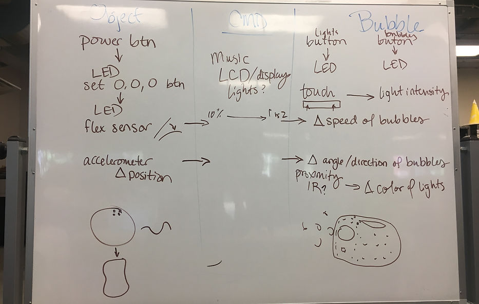
After determining the high-level functions of the system and its components, we split into our two-person teams and continued to flesh out the designs of the turret assembly and enclosure (see sketches below). The Bubble Maker’s shape and actionability depended on the method of bubble creation.After some discussion and searching on Amazon, we decided to buy three children’s bubble guns. We got the touch sensor strip, the buttons, the LED, and the servo motors in class. We received the motor and motor shield from Professor Brock. Mike had the Neopixels already, and we purchased the wood and flexible plastic from the CoMotion and Area 01’s makerspace stores.
 |  |  |
|---|---|---|
 |  |
The two biggest challenges our team faced were establishing proximity of XBees and using the stepper motor. First, in our project proposal we stated that we would use the distance between the Xbees of the Bubble Maker and the Controller Glove to adjust the color of the LED strip mounted to our enclosure. After much research, we determined that the XBee would have to use a special API mode in order to access the necessary data to determine the signal strength between modules. It turns out that signal strength is a less than accurate way of determining distance. Furthermore, using this API mode would have made communication much more complicated so we decided to abandon this feature all together. Second, the stepper motor was a particularly tricky piece of hardware to use. Each “step” in the motor’s rotation requires a sequence of commands with precisely timed pauses in between to create rotation. This precise timing presented a considerable number of problems when integrating the stepper code into the loop function without using delays. Unfortunately, we were unable to fully resolve this issue before the presenting the project but the process provided us with a valuable lesson in creating intricate timing without the use of delays.
Overall, some of the things we’d do differently if we did this project again would be to use different, less finicky bubble machines. We theorized that a larger reservoir with a propeller of bubble wands in front of a fan would be a more consistent method of bubble creation than pulling the trigger on childish bubble guns. Additionally, more effectively waterproofing of the NeoPixels in the front of the machine would have prevented the soapy liquid from frying two of the NeoPixels after the bubble machine was in use for a while. Also, with more time we may have been able to figure out being able to turn the platform motor more effectively and had a more interesting interaction with the glove in that way. Through the many challenges we were able to demonstrate that the system we designed was a viable prototype, which is very satisfying.